Fiber Optic Plates Selection Guide
What is Fiber Optic Plate (FOP)?
Fiber optic plate (FOP) is a component made of fused coherent fibers. It can precisely transmit image from input surface to output surface.
FOP can be used as Optical Isolator and Filter; it can absorb stray light during transmission and improving the SNR (signal to noise ratio).
FOP can be also used as a substrate of Xray Scintillator. It can absorb the excessive radiation which could do harm to the sensor.
In some other cases, FOP can used as coupler for complex design. for example: extraction image from a curve plane to a flat sensory surface.

Fiber optic plates with different shapes
Advantage of Fiber Optic Plate
With fiber optic plate, you can directly coupling image plane to the sensory surface. With this setup, light efficiency is improved, and save up more spaces for the apparatus. However, it is possible to acheive better image quality with a multiple lens system. But the price will be significantly higher than Fiber Optic Plate. (And also the weight)
The cost of Fiber Optic Plate
The price of fiber optic plate heavily depends on its geometry dimension and fiber(element) configuration.Usually, fiber optic plate under Ø25mm (diagonal) will quite affordable. The price could range from 5-15usd depending on the configuration.
And the price could be further reduced in a large quantity (e.g : 10K pcs)However, when the dimension goes beyond Ø100mm, the price will be increased a lot. (e.g: 1,000 US dollars+)
Getting start with Fiber Optic Plate
We strongly recommend buying some cheapy in-stock FOPs from us. Which can help you understand better about its characteristics.
We recommend below sample for initial test:
– Ø25mm Round Sample (4-6um mono Fiber size)
– 10mm x 10mm Square Sample (4-6um mono Fiber Size)
Different Configuration of Fiber Optic Plate
Standard Fiber Optic Plate (sFOP) >
– High Numerical Aperture (0.85 – 1.0)
– Absorb Stray Light
– Surface with different shapes (Concave, Plano, Convex…)
Low Numerical Aperture Fiber Optic Plate (lnaFOP) >
– Low Numerical Aperture (0.1 – 0.4)
– Use as angular filter
Dental Xray Fiber Optic Plate (dxFOP) >
– Protect Intra-oral sensor from Xray damage
– Substrate of scintillator
– Improving SNR (by absorbing stray light)
Radiation Hardening Fiber Optic Plate (rhFOP) >
– Protect sensor from heavy Xray penetration
Applications of Fiber Optic Plates
Intra-Oral Dental Sensor
Intraoral radiography is the most common type of radiographs among dental x-ray exams. It helps to detect decay between teeth and changes in the thickness of bone caused by gum disease as well as to identify the details of the upper and lower teeth in one area of the mouth. The most commonly used X-ray detectors for intraoral radiography is CsI(Tl) scintillation-based complementary metal–oxide–semiconductor (CMOS) photosensor array coupled with a fiber optic plate (FOP). The main purpose of the FOP is to absorb the x-ray which is not converted to visible light when traveling the
scintillator. However, the x-rays happen to directly hit the CMOS photosensor due to incomplete absorption of the x-rays within the FOP. Approximately 0.3% among the incident x-rays at 70 kVp can be transmitted to CMOS sensor.
High Speed X-Ray Imaging
X-ray detectors based on scintillators do not exist only as solid-state screens up to a size of 440mm x 440mm but also as semiconductor device where firstly the X-ray energy is converted into visible light, which is then converted into electrical signals. Figure below shows the photo of a CCD image sensor (1536 x 128 pixel) and the physical principle of the basic structure of an X-ray image detector based on scintillator material like CsI:Tl and light guides with aluminum walls. A fiber optic plate (FOP) with a CsI:Tl scintillator (FOS) is directly coupled to the CCD image sensor delivers up to 15 frames per second with a spatial resolution up to 6 Lp/mm.
Fluorescence imaging
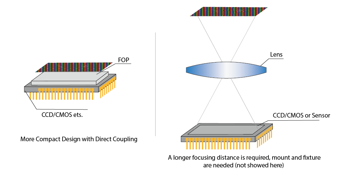
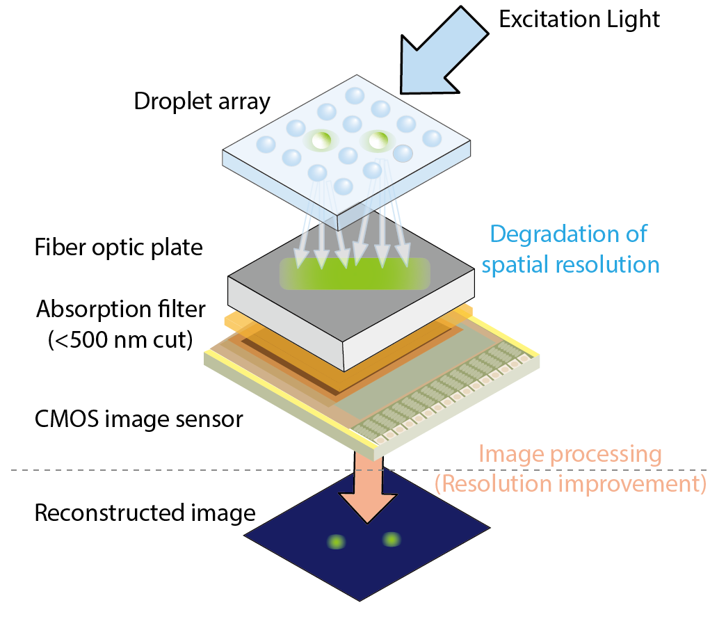
In the fluorescent imaging mode, the excitation light via a prism is reflected by total internal reflection (TIR) on the bottom of the glass substrate of a specimen. Some portion of the excitation light is scattered in the specimen on the surface of the droplets, microbeads, and glass substrates. These scattered light may not satisfy the TIR condition. To eliminate the scattered component, a yellow absorption filter is coated on the sensor. This filter is based on yellow dye and UV-curable polymer and the thickness is approximately 20 µm. Because the filter layer is fragile, a fiber optic plate is put on the device to protect the surface of the filter without degradation of spatial resolution.
Specifications of Fiber Optic Plates
Fiber Size
The diameter of mono fiber (or fiber monofilament). Usually smaller fiber size means a higher capable of transmit high resolution images.
Numerical Aperture
The numerical aperture of the fiber optic panel is the numerical aperture of the fiber monofilament. The numerical aperture of a fiber monofilament is only determined by the medium refractive index of the fiber core and cladding, and its size depends on the relative refractive index difference between the fiber core and cladding, and has nothing to do with the fiber geometry
Transmission
The transmittance performance of the fiber optic faceplate is the standard for evaluating the light transmission performance of the fiber optic panel, which is defined as the ratio of the outgoing luminous flux of the plate to the incident luminous flux.