


Product Configurations
0
Total items
$0.00
Taxes, discounts and shipping calculated at checkout
Product subtotal
Applications
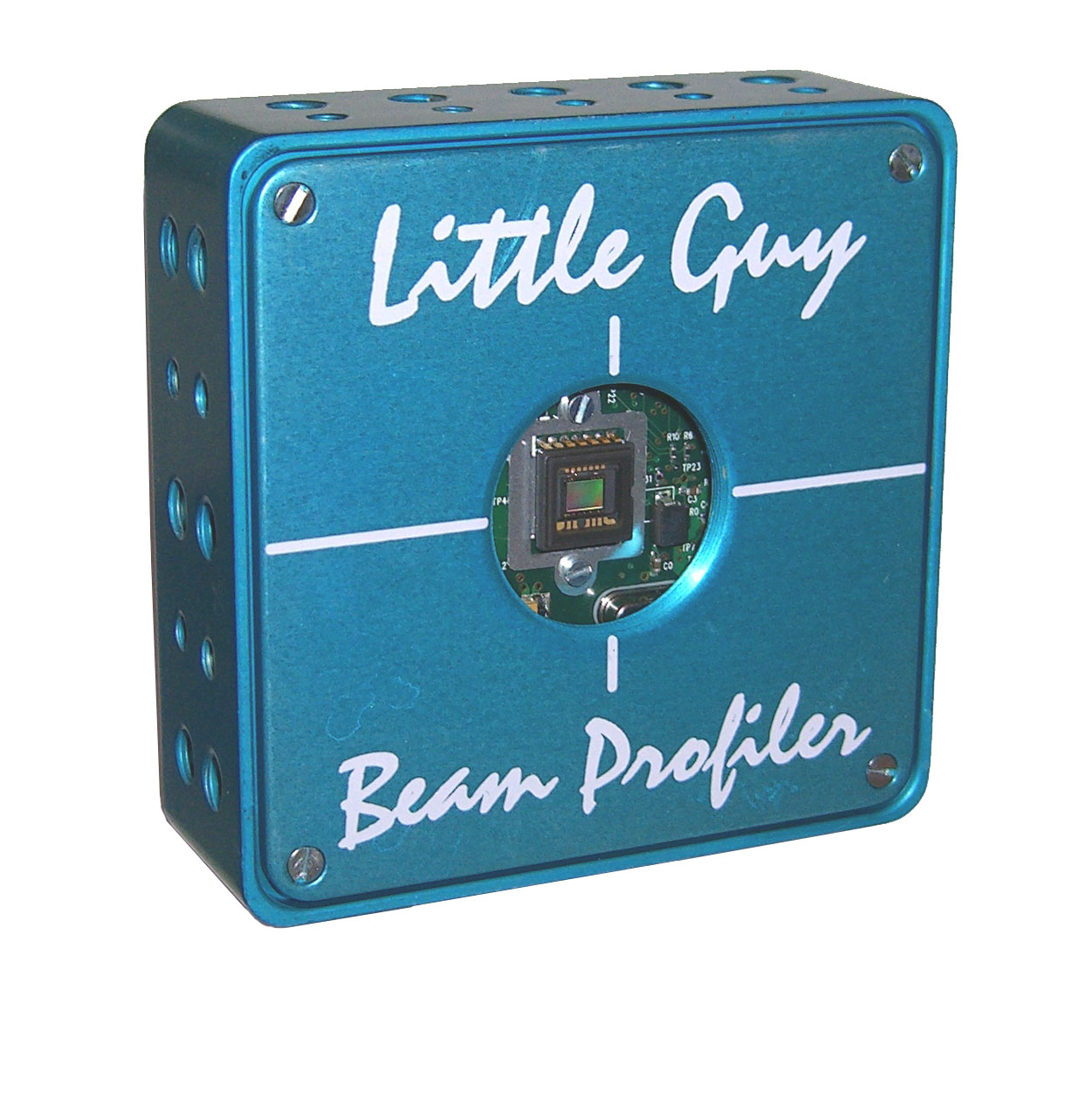
Beam Profiler
By integrating Fiber Optic Taper into the beam profiler, you can expand the sensory surface 2x - 3x easily.
- Compact Design (Compare with Lens)
- No Coma and Spherical Aberration
- Low Cost
- Easy Installation
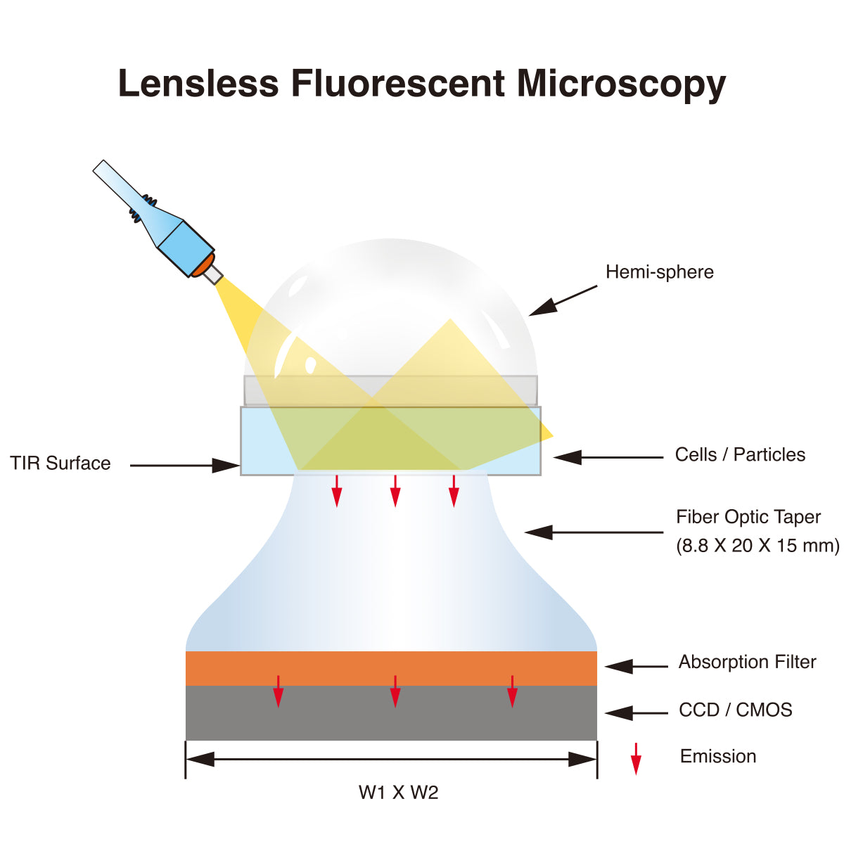
Fluorescent Imaging
Using Fiber Optic Taper in the Fluorescent Microscopy system you can increase the field of view of the microscope by capturing a larger area of the sample at the input end and projecting it onto a smaller area of the detector at the output end. This can improve the throughput and efficiency of the imaging system.
- Reduce Aberrations and Distortion
- Enhance Contrast
For more information, you can refer to the following web sources: