


Specifications
-

(大端)光纤直径
-

(小端)光纤直径
-

放大倍率
-

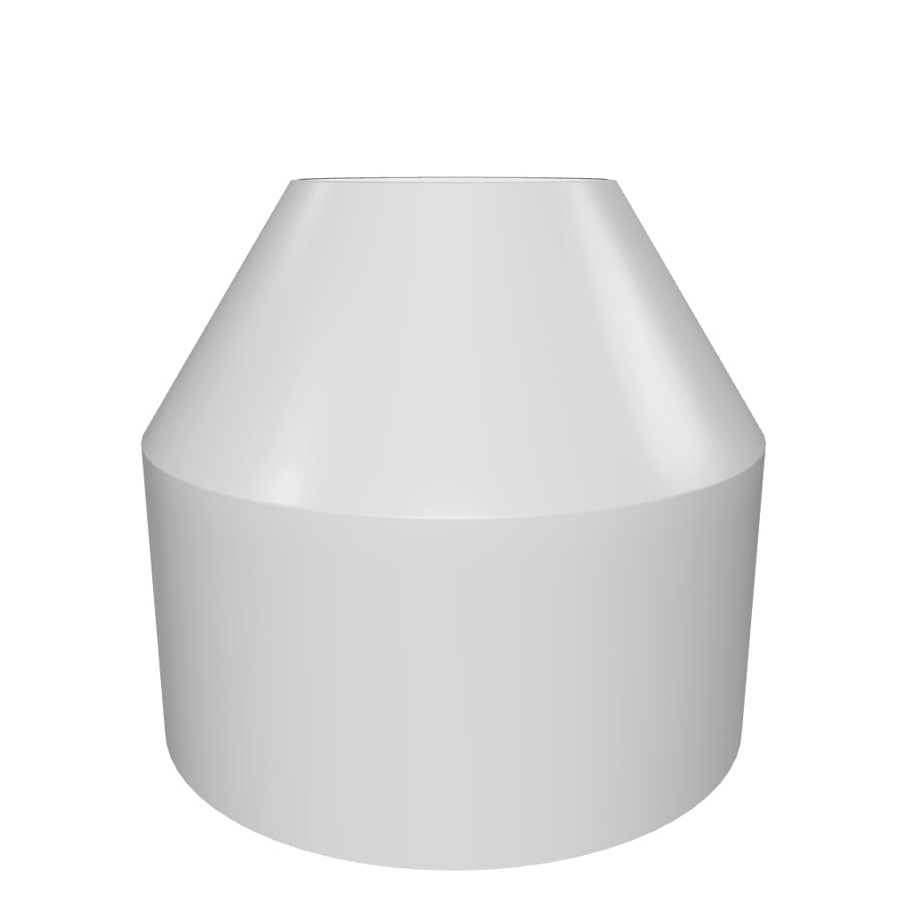
FOT的形状
-

数值孔径(N.A)


-
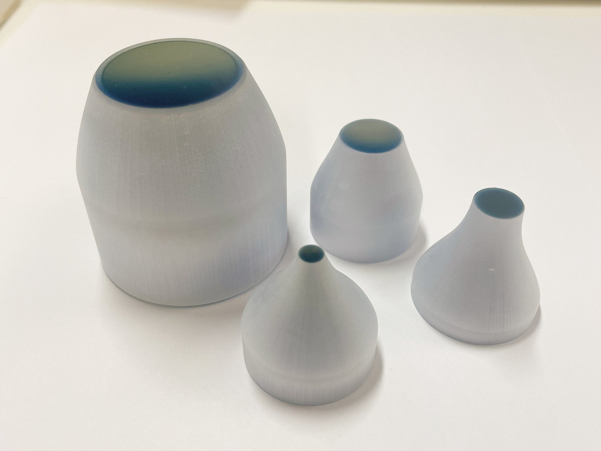
7倍放大倍率光纤锥
-

3倍放大倍率光纤锥
-

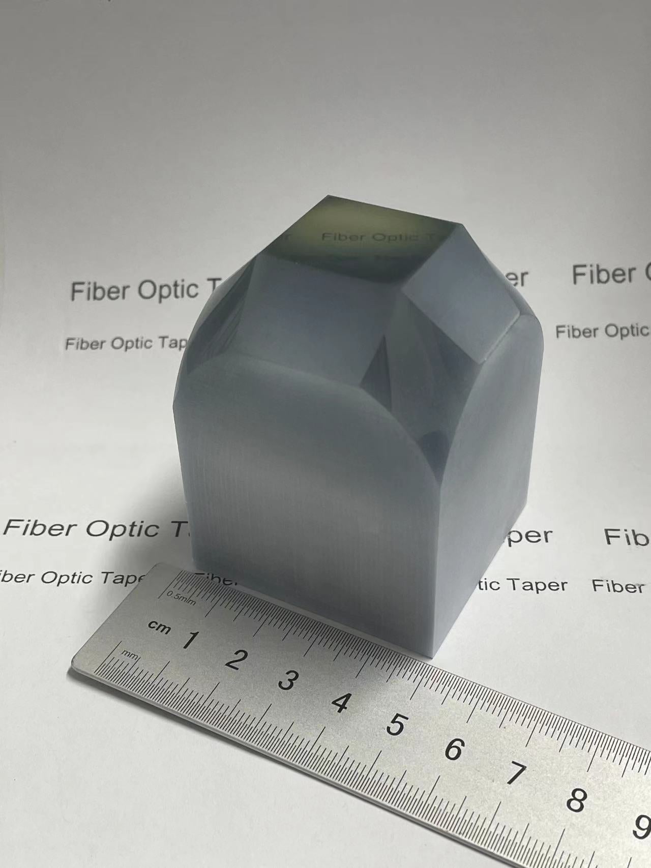
矩形表面光纤锥
-
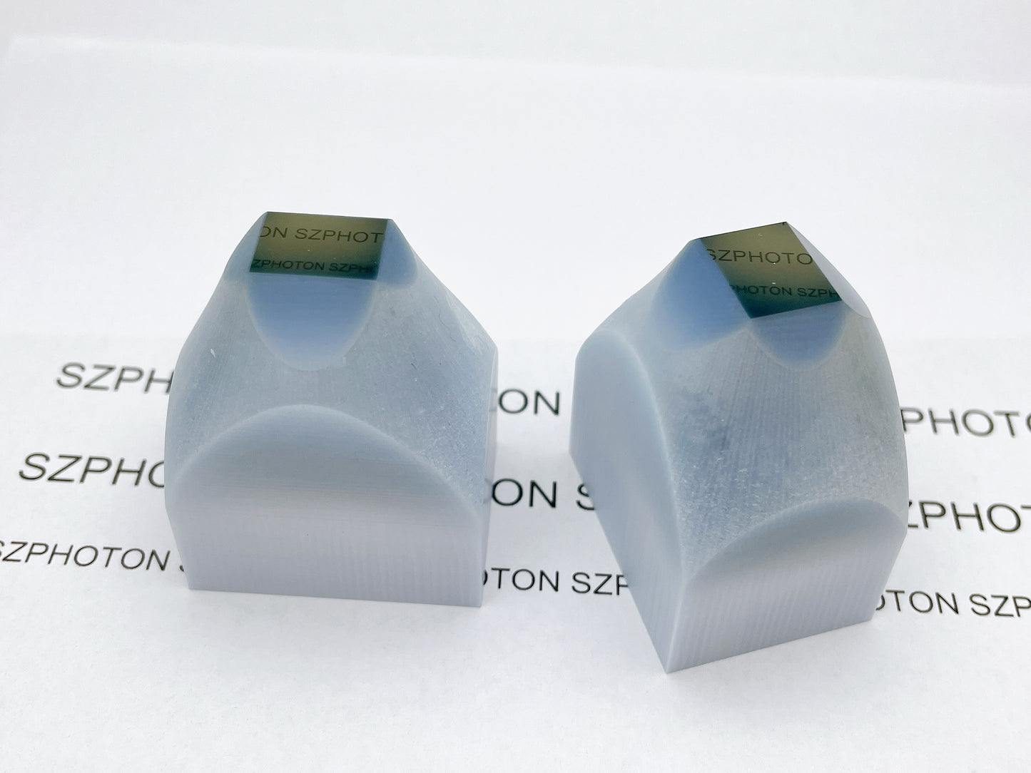
凹面光纤锥
-
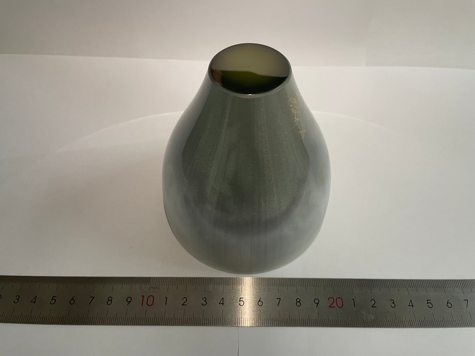
不同材质(俯视图)
-
不同材质(侧视图)
-

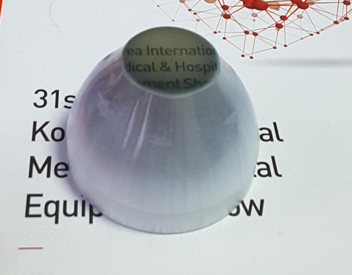
不同材质(底部视图)


-

光束分析仪
-

荧光成像

