


Specifications
-

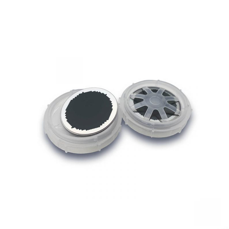
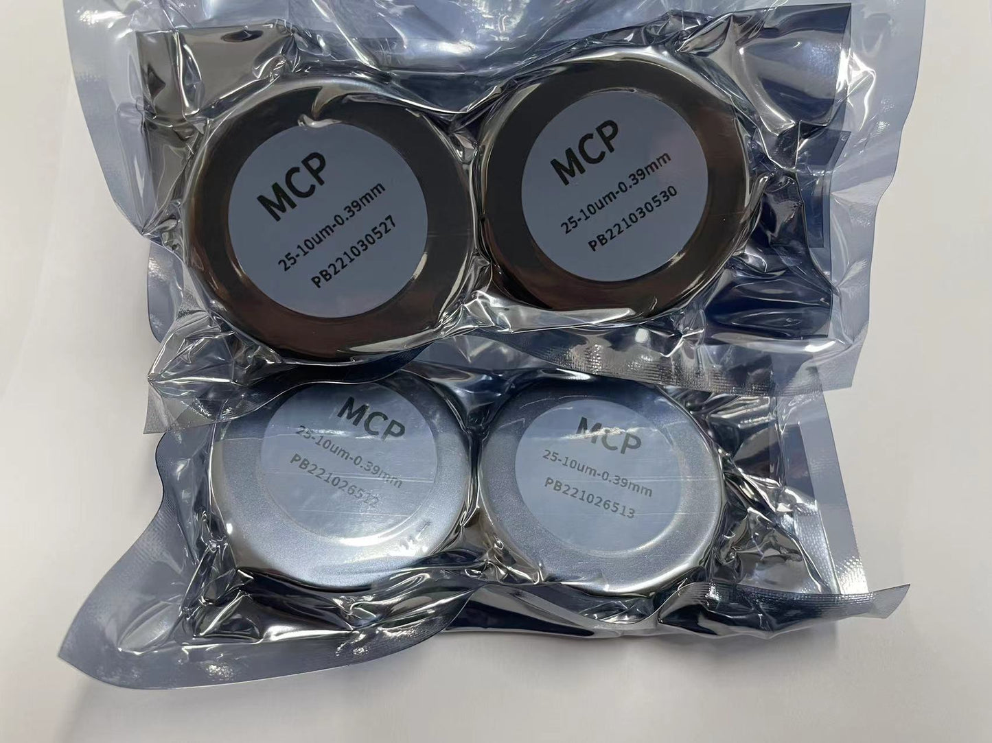
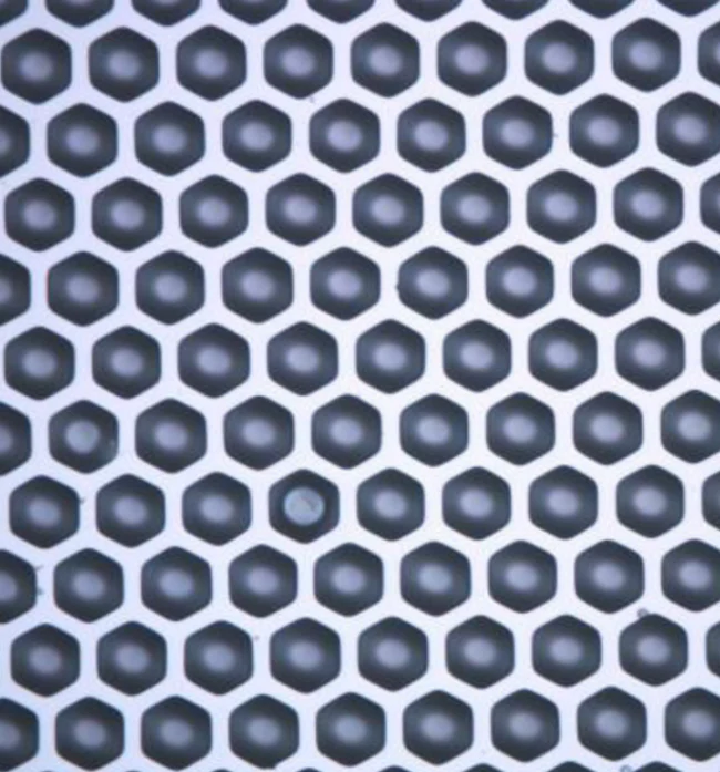
Dimension of MCP
-

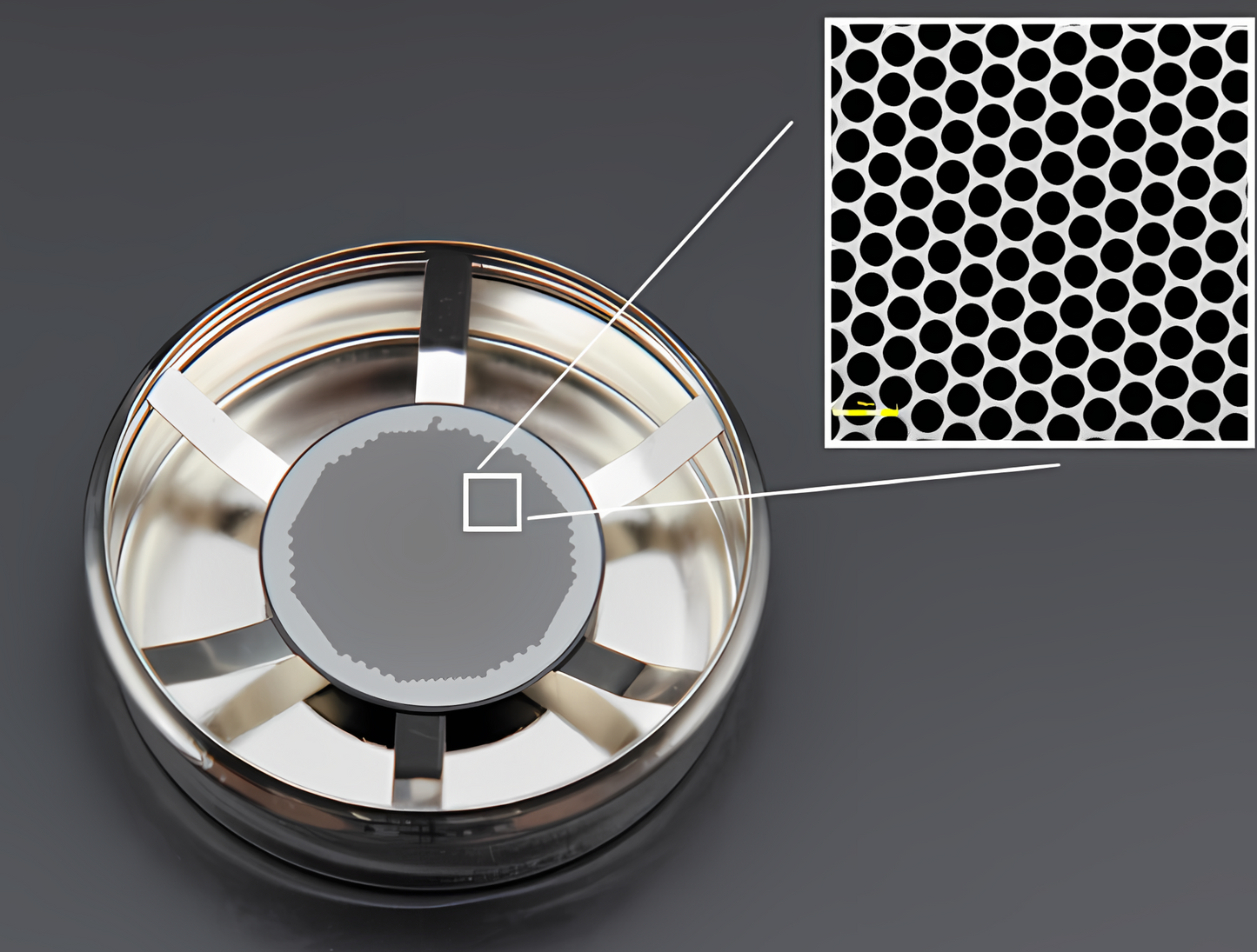
L/D Ratio
-

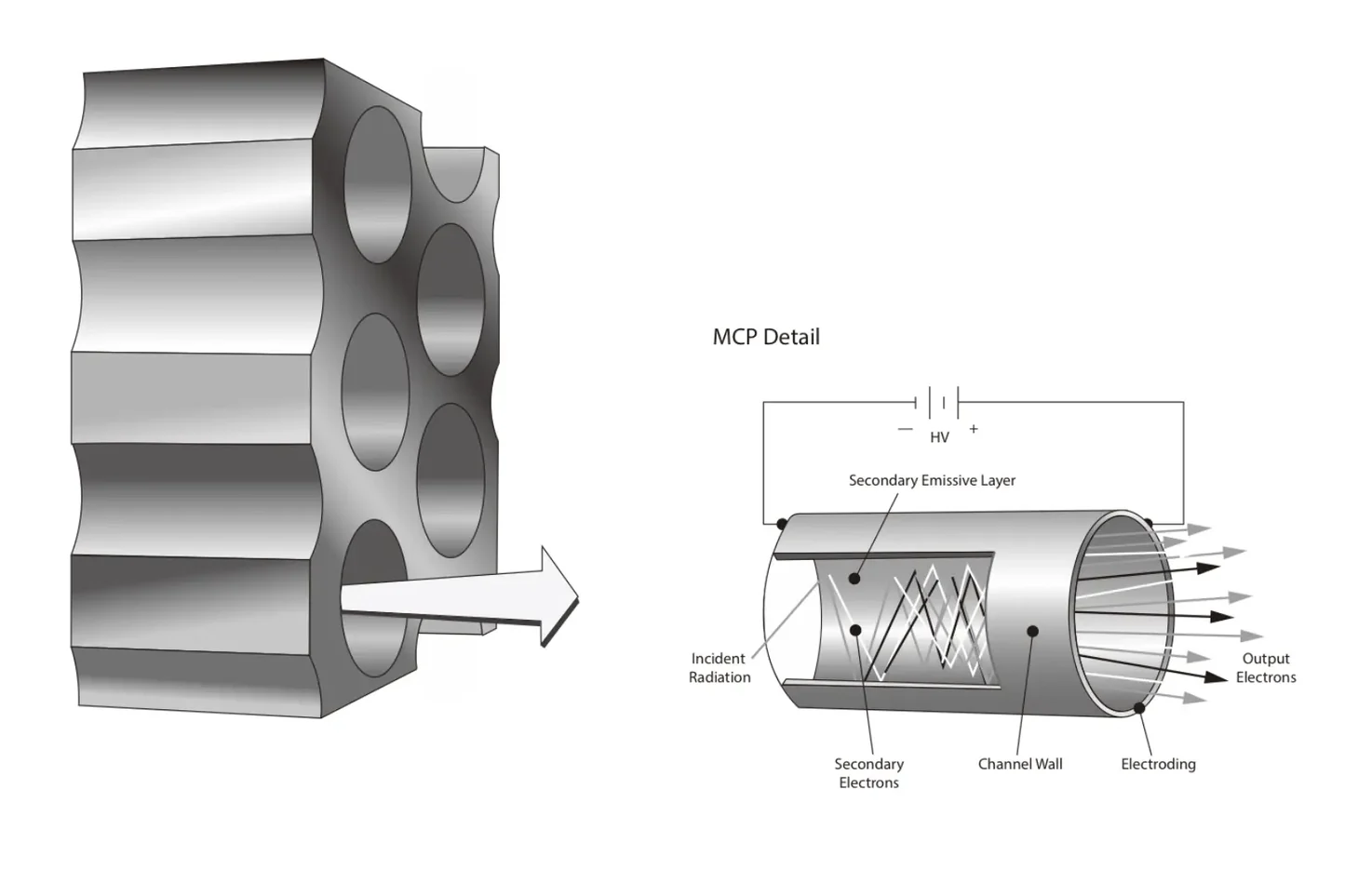
Stacking the MCPs


-

Image Intensifiers
-

Working Principles

